Overview
- Controller for intro to S7 with basic expansion options
- Expandable by:
- 1 signal board (SB), battery board (BB) or communication board (CB)
- 2 signal modules (SM)
- Max. 3 communication modules (CM)
Design
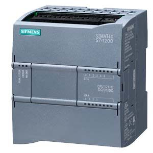
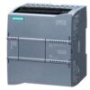
The compact CPU 1212C has:
- 3 device versions with different power supply and control voltages.
- Integrated power supply either as wide-range AC or DC power supply (85 … 264 V AC or 24 V DC)
- Integrated 24 V encoder/load current supply:
For direct connection of sensors and encoders. With 300 mA output current also for use as load power supply. - 8 integrated digital inputs 24 V DC (current sinking/current sourcing (IEC type 1 current sinking)).
- 6 integrated digital outputs, either 24 V DC or relay.
- 2 integrated analog inputs 0 … 10 V.
- 2 pulse outputs (PTO) with a frequency of up to 100 kHz.
- Pulse-width modulated outputs (PWM) with a frequency of up to 100 kHz.
- Integrated Ethernet interface (TCP/IP native, ISO-on-TCP).
- 4 fast counters (3 with max. 100 kHz; 1 with max. 30 kHz), with parameterizable enable and reset inputs, can be used simultaneously as up and down counters with 2 separate inputs or for connecting incremental encoders.
- Expansion by additional communication interfaces, e.g. RS 485 or RS 232.
- Expansion by analog or digital signals directly on the CPU via signal board (with retention of CPU mounting dimensions).
- Expansion by a wide range of analog and digital input and output signals via signal modules.
- Optional memory expansion (SIMATIC Memory Card).
- PID controller with auto-tuning functionality.
- Integral real-time clock.
- Interrupt inputs:
For extremely fast response to rising or falling edges of process signals. - Removable terminals on all modules.
- Simulator (optional):
For simulating the integrated inputs and for testing the user program.
|
Device versions |
||||
|---|---|---|---|---|
|
Version |
Supply voltage |
Input voltage DI |
Output voltage DO |
Output current |
|
24 V DC |
24 V DC |
24 V DC |
0.5 A, transistor |
|
24 V DC |
24 V DC |
5 … 30 V DC / |
2 A; |
|
85 … 264 V AC |
24 V DC |
5 … 30 V DC / |
2 A; |
Function
- Comprehensive instruction set:
A wide range of operations facilitate programming:- basic operations such as binary logic operations, result allocation, save, count, create times, load, transfer, compare, shift, rotate, create complement, call subprogram (with local variables)
- integral communication commands (e.g. USS protocol, Modbus RTU, S7 communication “T-Send/T-Receive” or Freeport)
- user-friendly functions such as pulse-width modulation, pulse sequence function, arithmetic functions, floating point arithmetic, PID closed-loop control, jump functions, loop functions and code conversions
- mathematical functions, e.g. SIN, COS, TAN, LN, EXP
- Counting:
User-friendly counting functions in conjunction with the integrated counters and special commands for high-speed counters open up new application areas for the user - Interrupt processing:
- edge-triggered interrupts (activated by rising or falling edges of process signals on interrupt inputs) support a rapid response to process events.
- time-triggered interrupts.
- counter interrupts can be triggered when a setpoint is reached or when the direction of counting changes.
- communication interrupts allow the rapid and easy exchange of information with peripheral devices such as printers or bar code readers
- Password protection
- Test and diagnostics functions:
Easy-to-use functions support testing and diagnostics, e.g. online/offline diagnostics - “Forcing” of inputs and outputs during testing and diagnostics:
Inputs and outputs can be set independently of cycle and thus permanently, for example, to test the user program - Motion Control in accordance with PLCopen for simple movements
- Library functionality
Programming
The STEP 7 Basic programming package permits complete programming of all S7-1200 controllers and the associated I/O.
